Force-Controlled Gripper
A DIY gripper that controls how hard it squeezes, for under $40
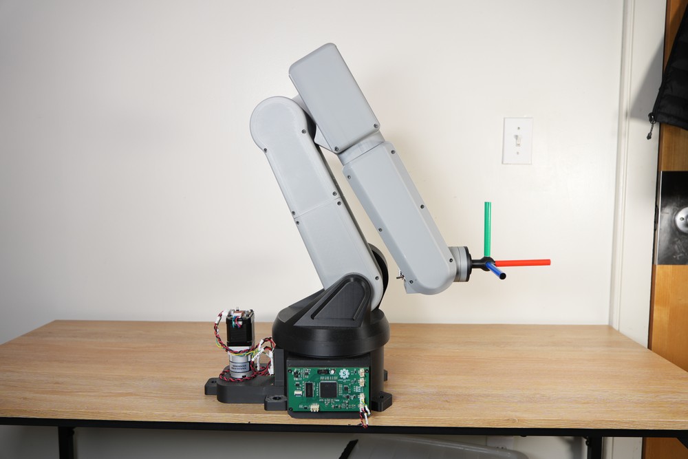
Once our robot arm was working, it needed a hand. Most DIY grippers just open and close, but we wanted one that could control how hard it squeezes. That way the same gripper can hold a 3D-printed cube firmly and still pick up a potato chip without crushing it. The whole thing cost $36.48.
My brother Steve designed the controller and the PCB. I did all of the mechanical design and the assembly, and I built the test rig we used to measure the motor's torque. Steve has a write-up that covers the controller and the electrical side in detail. On this page I'm going to cover the mechanical design and the current loop, because together they're what turn motor current into grip force.
Why Force Control?
Most DIY grippers run on a hobby servo, the kind that comes in an Arduino kit. The problem is that you can only tell a servo where to go, not how hard to push. It just pushes as hard as it can until it gets there. That's fine for a block of wood, but not so great for a potato chip.
Grippers that can control force usually use a brushless motor and an FOC driver. That works really well, but good FOC drivers are expensive. Source Robotics' SSG-48 gripper, for example, sells for €599.
Steve came up with a cheaper idea in spring 2026, while he was taking an electric drives course. During a lab on controlling DC motors, he realized a plain brushed DC motor could do the same job for a fraction of the price.
Mechanical Design
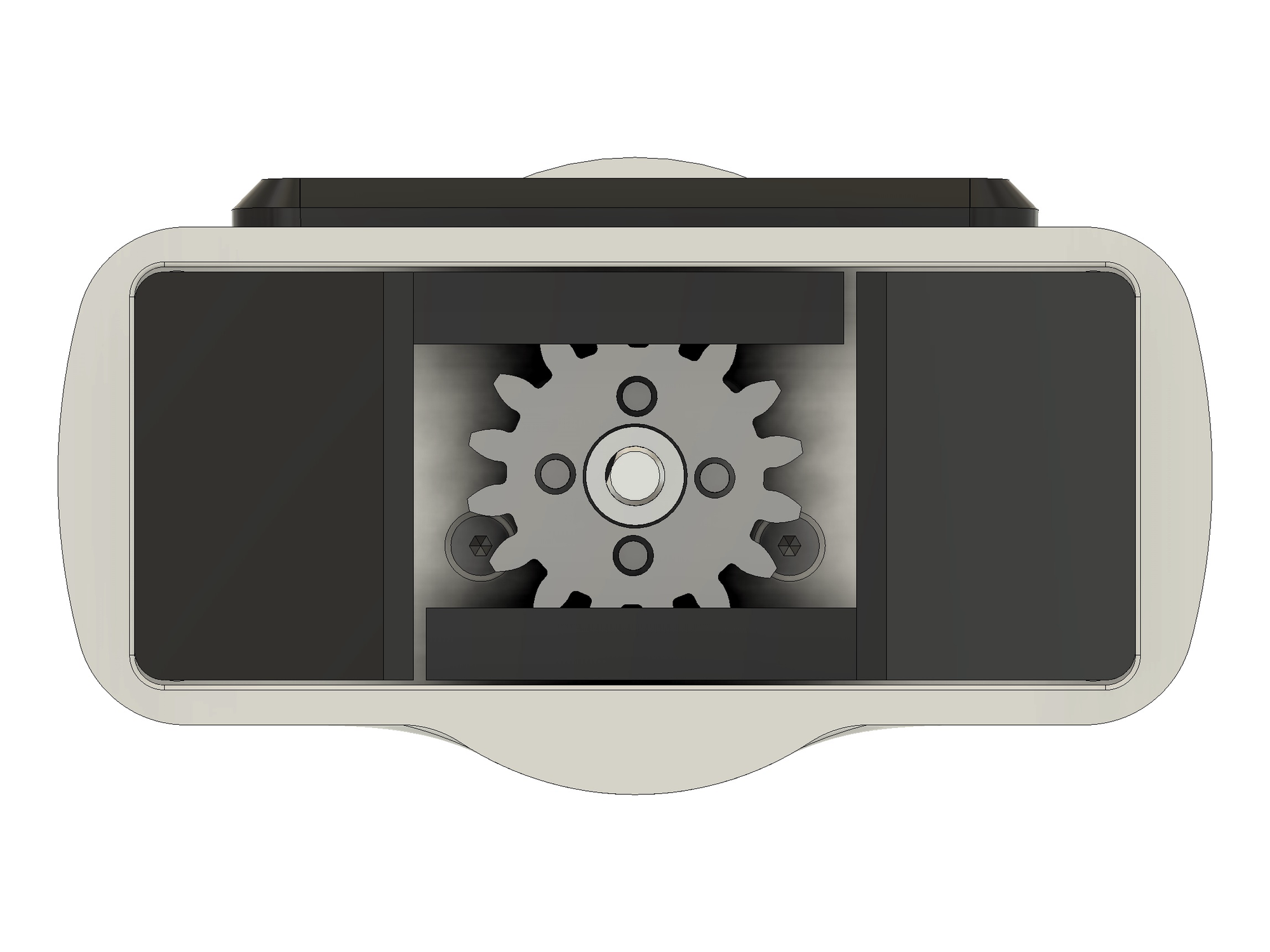
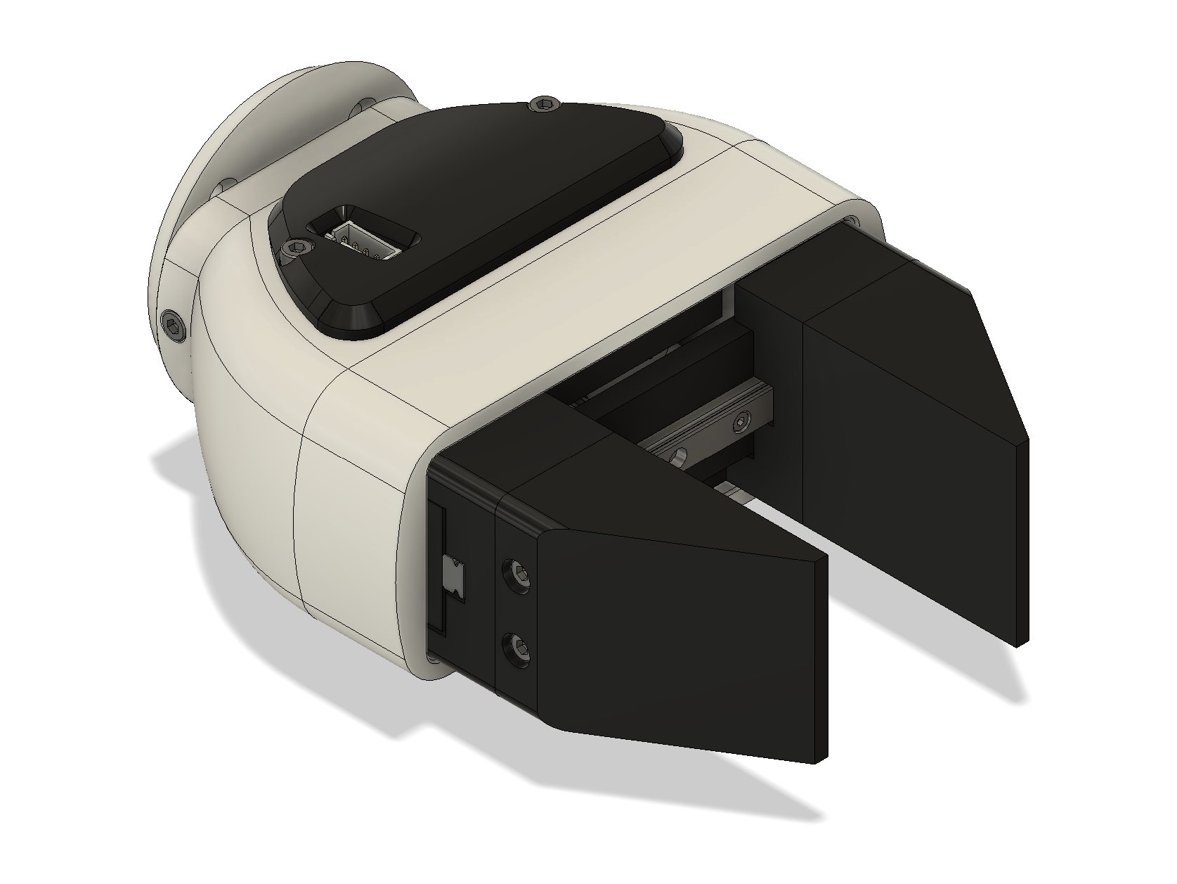
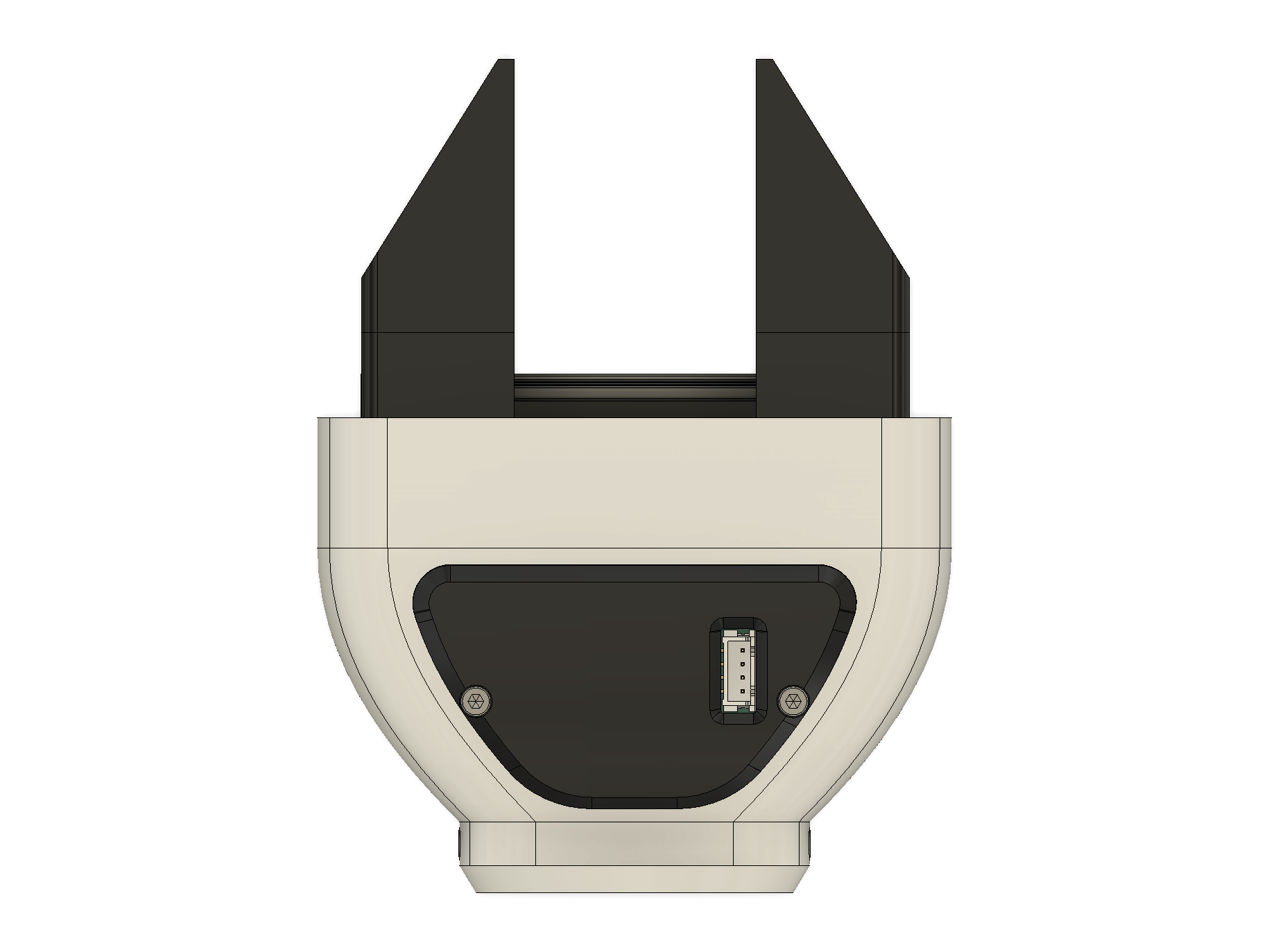
The motor spins, but the jaws need to slide in a straight line. The simplest way to turn rotational motion into linear motion is a rack and pinion. The pinion is a gear on the motor's output shaft, and the rack is a straight strip of teeth on the jaw. As the pinion turns, it pushes the rack along, and the jaw slides with it.
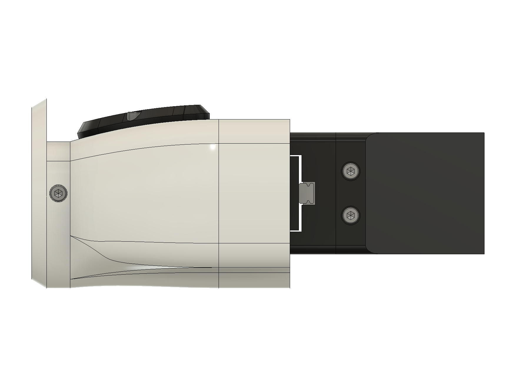
Both jaws move, so each one has its own rack. The two racks sit on opposite sides of the pinion, so when the pinion turns, it drives them in opposite directions. The jaws always move the same distance toward or away from each other, which keeps the gripper centered on whatever it's holding. Each jaw is mounted on a carriage that rides along a 100 mm linear rail. The rail takes the side loads and twisting, so the rack and pinion only has to push the jaws along it.
Grip force
The pinion is a 16-tooth spur gear with a module of 1.889 mm. The pitch diameter is the module times the number of teeth, so its pitch radius \(r\) is:
A rack and pinion works like a wheel rolling along the ground. When the pinion turns through an angle \(\theta\), each rack moves by the arc length at the pitch circle. Since the two jaws move in opposite directions, the gap between them closes twice as fast:
Torque works the same way in reverse. When the jaws close on an object, the object pushes back on each jaw with a force \(F\), and that force acts on the pinion at the pitch radius. There are two racks, so the torque from the motor gets shared between them:
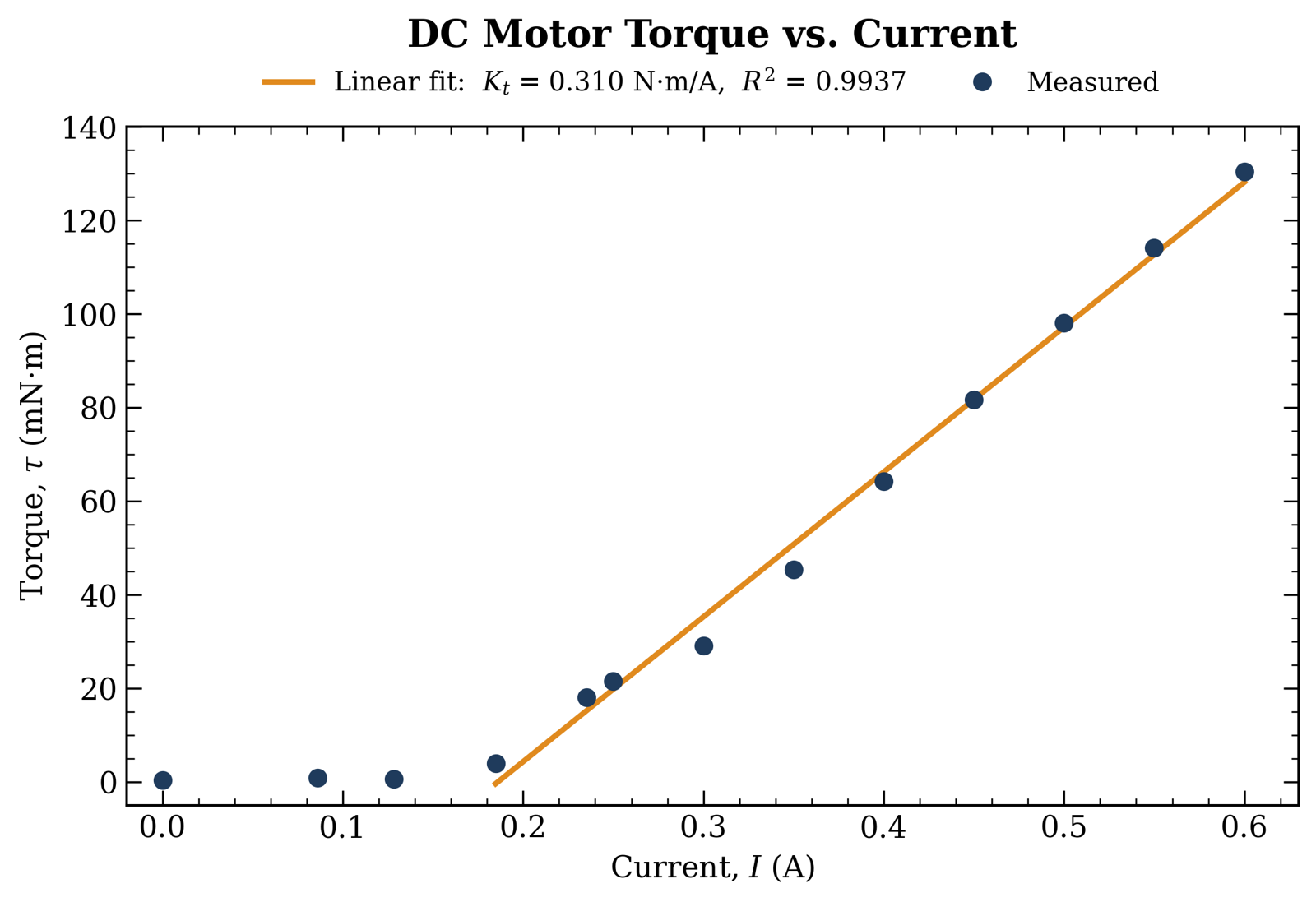
This is the key equation for the whole gripper. The grip force is just the motor's torque scaled by a fixed number set by the gear, so if we can control the torque, we can control the force. And as the next section shows, a DC motor's torque is set by its current. On the test rig we measured 0.310 N·m/A at the gearbox output, once the current gets past the gearbox friction. The fitted line crosses zero torque at about 0.19 A, which we'll call \(i_0\). Putting it all together gives the grip force straight from the current:
So every extra amp of current adds about 10 N of squeeze on each jaw. At 0.6 A, we measured 130 mN·m of torque, which works out to about 4.3 N per jaw. This ignores any losses in the rack and pinion itself.
The jaws don't hold things by squeezing alone. It's the friction from that squeeze that stops an object from sliding out. Each jaw gives a friction force of up to \(\mu F\), and there are two jaws, so the heaviest object the gripper can hold is:
Here \(\mu\) is the friction coefficient between the jaws and the object, so how much the gripper can hold depends on what it's picking up. A heavier or more slippery object needs more current, and a fragile one like a chip needs just enough current to hold it without breaking it.
Control Design
The reason a DC motor works here is that its torque is proportional to the current going through it:
Here \(\tau\) is the torque, \(i\) is the current, and \(k_T\) is a constant for the motor. If you can control the current, you can control the torque, and that means you can control the grip force. So the whole gripper really comes down to one job: holding the motor current at whatever value we ask for. There are also speed and position loops wrapped around it for opening and closing the jaws, but the current loop is what does the gripping, so that's what I'll walk through.
Motor model
Electrically, a DC motor behaves like a resistor, an inductor, and a voltage source all in series. If you add up the voltages around that loop, you get:
\(V_a\) is the voltage we apply, \(R_a\) and \(L_a\) are the resistance and inductance of the windings, and \(e_b\) is the back EMF. Back EMF is a voltage the motor makes as it spins, and it grows with speed (\(\omega\)). It's the reason you can't just set a voltage and call it a day. Put 3 V across the motor and you'll get one current when it's stalled and a much smaller current once it starts spinning.
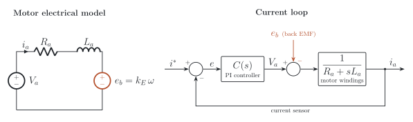
The good news is that back EMF changes a lot more slowly than the current does. So instead of modeling it, we treat it as an outside disturbance that the controller has to push against. Once you drop it and take the Laplace transform, you're left with a simple first-order transfer function from voltage to current:
We measured our motor ourselves: \(R_a\) came out to 3.0 Ω at stall, and \(L_a\) was 3.5 mH on an LCR meter. That gives an electrical time constant \(\tau_e\) of 1.17 ms, which puts the motor's only pole at 857 rad/s (about 136 Hz).
PI controller
There's no integrator in this transfer function, which makes it what's called a type 0 system. In practice, that means a plain proportional controller would always leave the current sitting a little below the target. Adding an integral term fixes that, since the integral keeps building up until the error is zero. So we went with a PI controller:
Writing it the second way shows that the PI controller adds a zero at \(s = -k_i/k_p\). That zero ends up being what makes tuning so easy.
Gain selection
If we put the controller's zero right on top of the motor's pole, by setting \(k_i/k_p = 1/\tau_e\), the two cancel each other out. What's left of the open-loop transfer function is just a pure integrator:
An integrator is about the nicest loop you can ask for. Its gain drops at a steady 20 dB per decade, and its phase sits at −90° at every frequency. That means the phase margin is 90° wherever the crossover lands. Once you close the loop, the current follows the setpoint smoothly, with no overshoot.
Cancelling the pole only sets the ratio between the two gains, though, so we need one more equation to pin them down. If we pick a crossover frequency \(\omega_c\) and set the loop gain to 1 there, we get both gains:
Crossover frequency
So why not just make \(\omega_c\) as high as possible? Because the real loop isn't a perfect integrator. Every cycle, the microcontroller measures the current and calculates a new voltage, but that voltage doesn't reach the motor until the next PWM update. The filter on the current sensor adds a bit more lag on top of that. Both of these eat into the phase margin, and they get worse the higher the frequency goes. A common rule of thumb is to keep the crossover 1 to 2 decades below the switching frequency.
Our PWM runs at 25 kHz, so we set the current loop crossover to 1 kHz. Plugging in our measured motor values gives \(k_p\) = 22 V/A and \(k_i\) = 18,850 V/(A·s). One last detail: the controller outputs a voltage, and the firmware turns that into a PWM duty cycle by dividing by the supply voltage. That way the PWM stage just looks like a gain of 1 to the controller.
Hardware
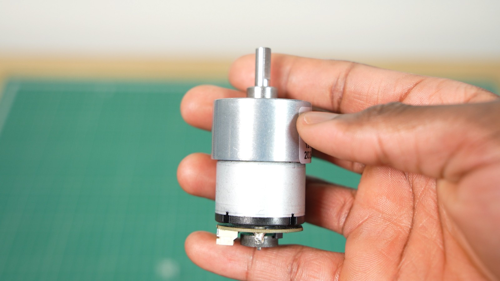
For the motor, we used a JGB37-520 geared DC motor from AliExpress ($12.18). A small DC motor doesn't make much torque on its own, so the built-in gearbox helps a lot, and it comes with an encoder on the back that we use for position.
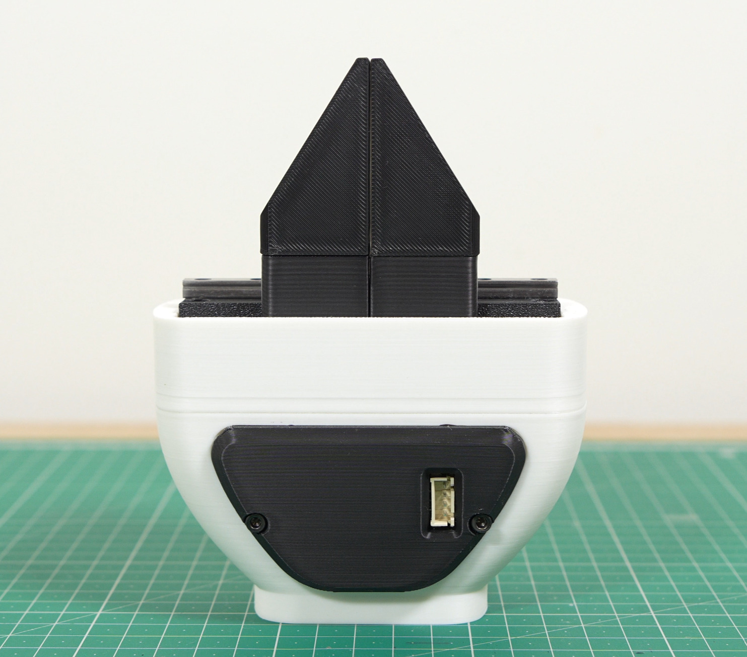
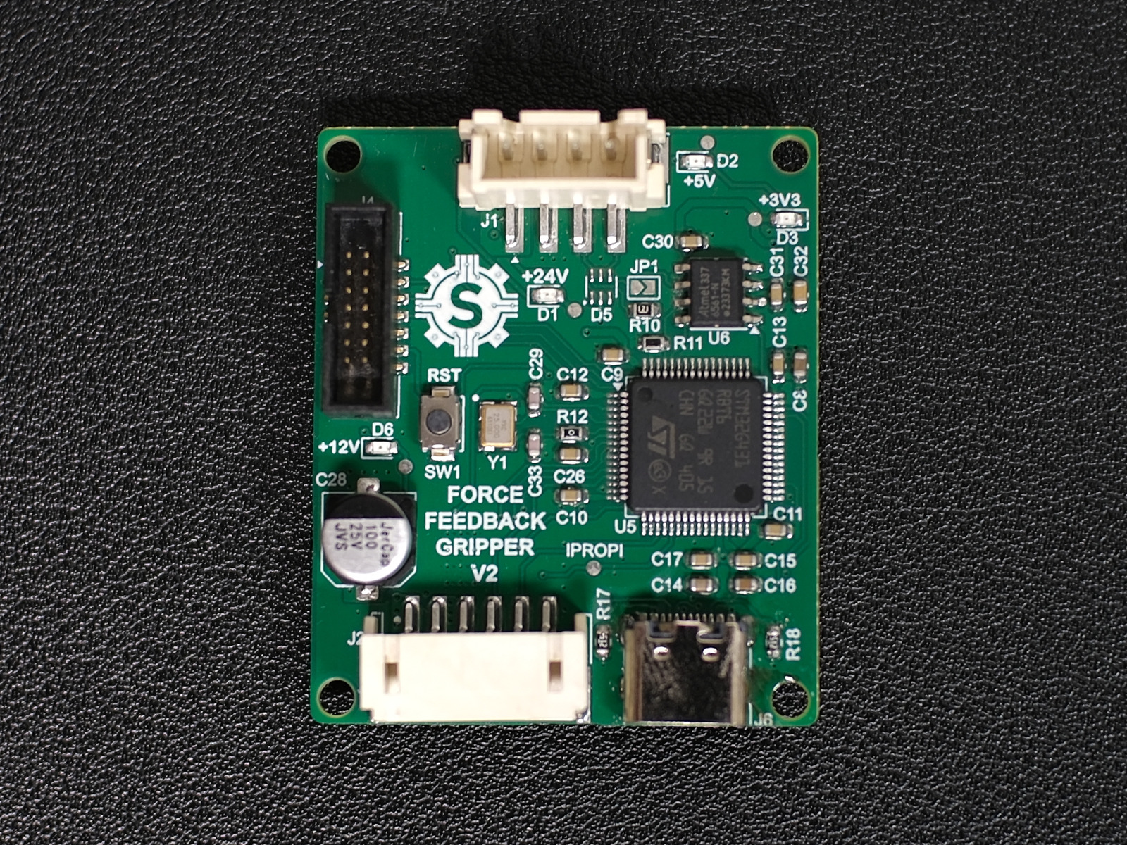
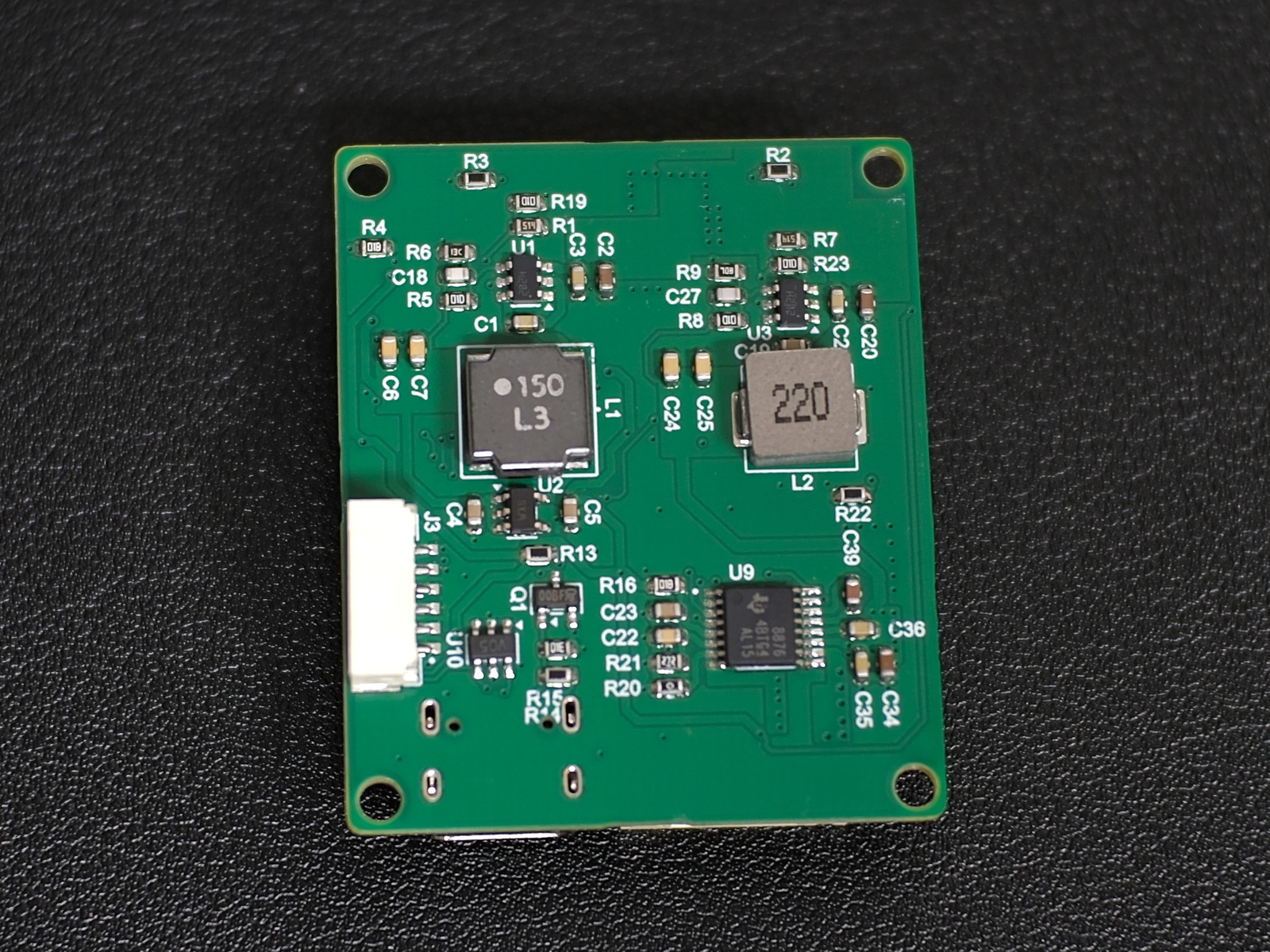
Steve designed a custom PCB to drive it. An STM32G431 runs the controller, and a DRV8876 drives the motor. He picked the DRV8876 because it measures the motor current on its own, so we didn't need a separate current-sense resistor. The catch is that it can't measure current flowing backwards, which happens when the motor acts like a generator. That doesn't really matter for us, since the motor is stalled against the object while it's gripping.
Testing
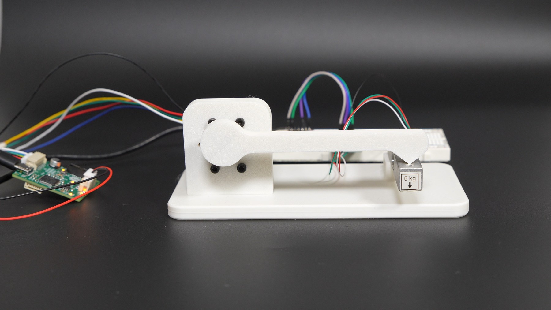
To make sure the current actually turned into a predictable torque, I built a test rig. A 3D-printed lever arm on the motor shaft presses down on a 5 kg load cell, and an ESP32 reads the load cell. We stepped through a range of current setpoints and recorded the torque at each one.
Up to about 150 mA, the torque barely changed. All of that current was going into overcoming friction in the gearbox. Past that point, torque rose in a straight line with current, at 0.310 N·m/A with an R² of 0.994. At 0.6 A we measured about 130 mN·m. To make up for the friction, Steve added a dead zone to the controller.
And of course, if you turn the current up, it'll crush the chip too:
Cost
| Item | Cost |
|---|---|
| JGB37-520 DC motor | $12.18 |
| PCB components | $9.30 |
| 100 mm linear rail (comes with one carriage) | $6.00 |
| Second carriage | $4.00 |
| 3D-printed parts | $3.00 |
| PCB | $1.00 |
| Flange coupling | $1.00 |
| Total | $36.48 |
There's still room to bring the cost down. The STM32G431 ($5.81) is way more chip than this job needs, and ST's new STM32C5 line costs about $2 and would do just fine. Steve stuck with the G4 because it's the same chip he used on our robot arm's joint drivers, so he could reuse a lot of that code.
Conclusion
This project came down to one simple idea: control the current and you control the force. With a cheap geared DC motor, a board that cost about $10, and a properly tuned current loop, we ended up with force control that usually costs $100 or more. Honestly, it worked better than we expected. If you want to see the full controller and electrical design, check out Steve's write-up.
Thanks for reading!