Automated Stator Winding Machine
A flyer winder that lays orthocyclic coils for my actuators
I want to build my own actuators, and if I'm going to build a robot, I need a lot of them. Every actuator needs a wound stator, and winding stators by hand is slow and hard to do neatly. So I set out to build a machine that winds them for me. This page covers how I designed it, the winding pattern it uses, and the problems I've been fixing since the first test. It's still a work in progress.
Goals
- Wind stators automatically, so I don't have to wind every stator by hand
- Pack the wire as tightly as possible, using orthocyclic winding
- Control the wire tension, since a loose wire tangles
- Reuse hardware I already have, like the stepper drivers from our robot arm
Design
Jaw mechanism
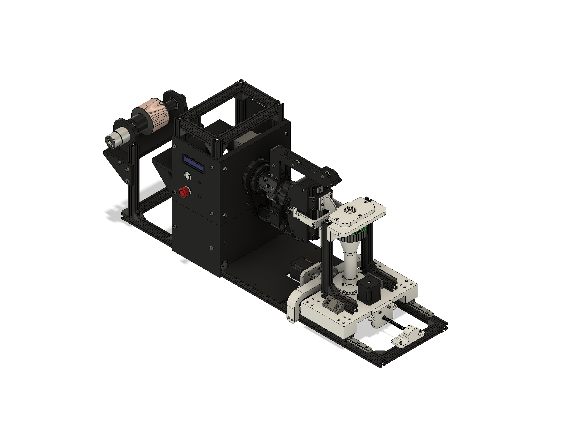
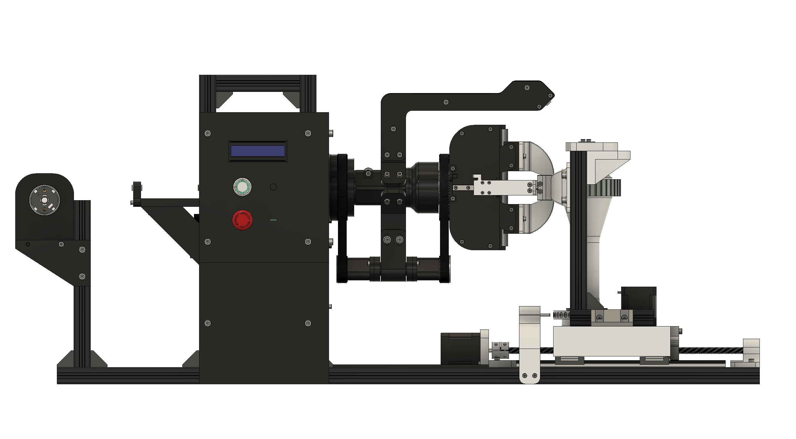
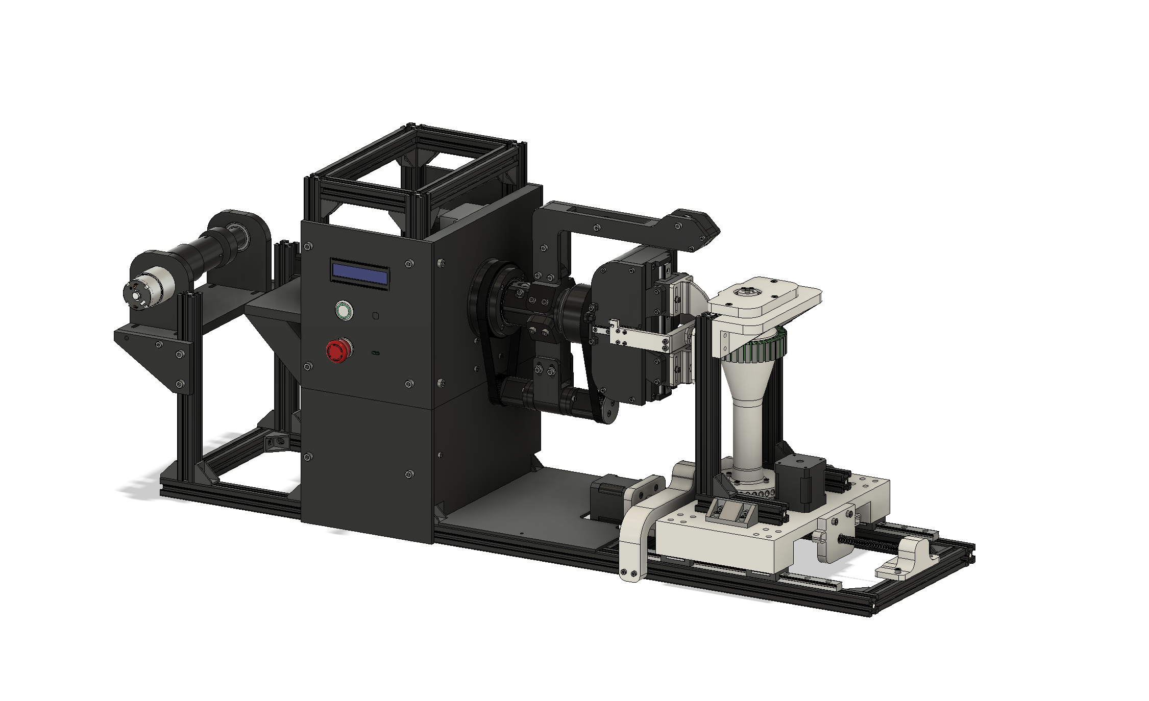
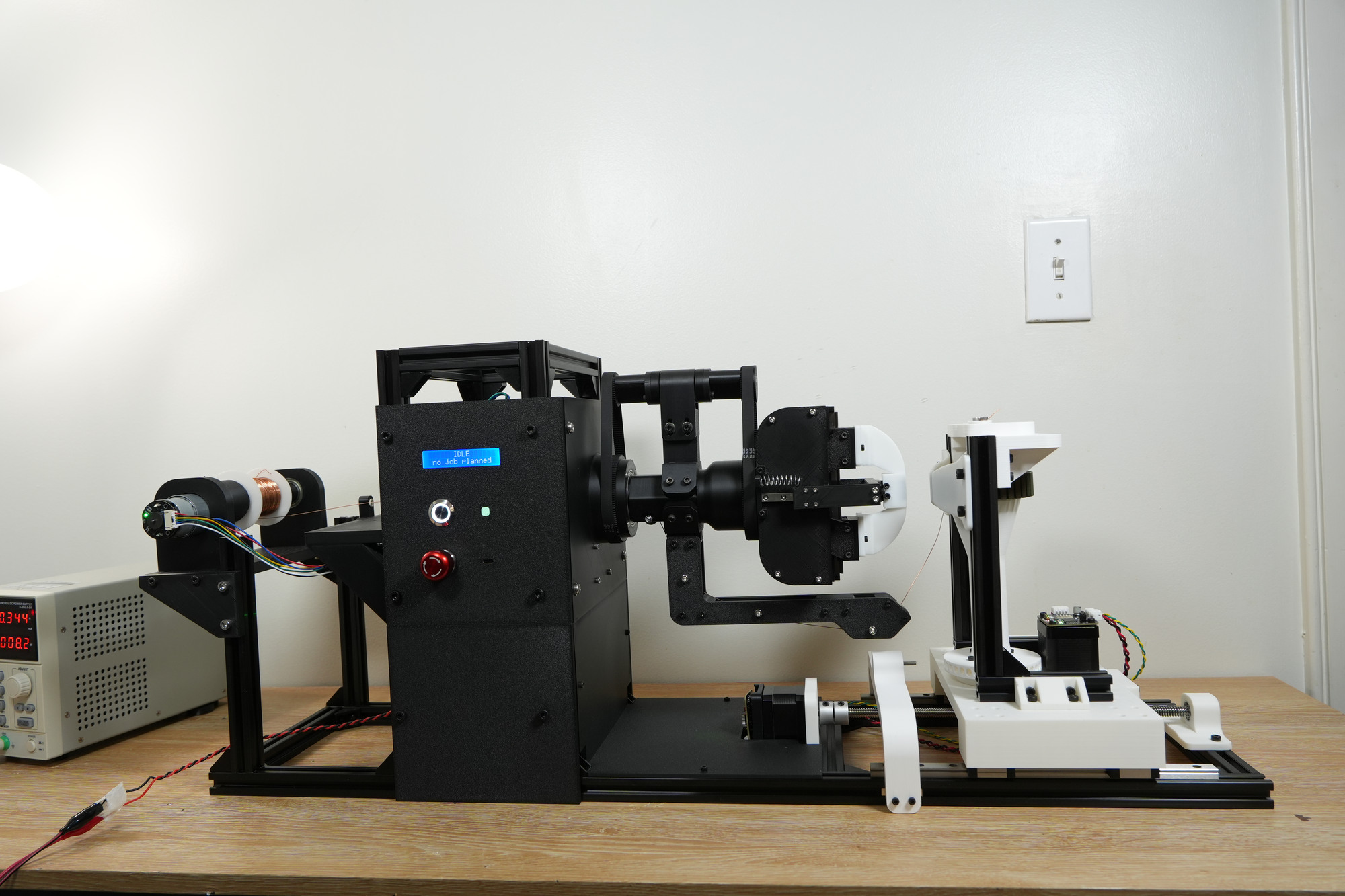
My machine winds each coil with a flyer, a spinning arm that carries the wire around the tooth. While the flyer spins, the stator sits on a traverser that slides it over by one wire width every turn, so each new turn lands right next to the last one.
The winding head has a pair of jaws that guide the wire, and they need to open and close. The simplest way to do that would be a small motor on the head. The problem is that the head spins, so the motor's power wires would spin with it and get wound onto the tooth along with the copper wire.
Running the motor's wires down the center rod doesn't fix it. The head still spins, so the wires twist a little more with every turn.
I needed to work the jaws from a distance. The jaws are spring-loaded, and a rod pushes against them. The jaw mechanism turns that pushing motion along the rod into the jaws opening, so pushing the rod opens the jaws, and letting go lets the spring close them. No wires on the spinning head at all.
Pulley train
That created a new problem: how do you push on a rod and feed wire while the head around it is spinning?
My solution uses two belt-and-pulley sets, each with a large pulley and a small pulley. The large pulley of the first set is fixed to the frame. The two small pulleys are locked together on a shaft that rides around with the flyer, so as the flyer spins, both small pulleys orbit around their large pulleys. Both sets have the same ratio, and that's the whole trick. Every turn of the flyer carries the small pulleys around once, which on its own would drag the second large pulley forward one turn. But the belt on the fixed pulley also makes the small pulleys spin as they orbit, and with matching ratios, that spin turns the second large pulley back by exactly one turn. The two cancel out, so the second large pulley doesn't turn at all. It stays still while the flyer spins around it.
If you work it out, the second large pulley turns at:
\(Z_B\) and \(Z_s\) are the tooth counts of the large and small pulleys in each set. When both sets have the same ratio, the term in brackets is exactly zero, so \(\omega_{\text{out}} = 0\) no matter how fast the flyer spins.
That still point is what makes everything else work. The center rod can slide back and forth to open the jaws, and the wire can still be routed out to the flyer for winding.
Wire tension
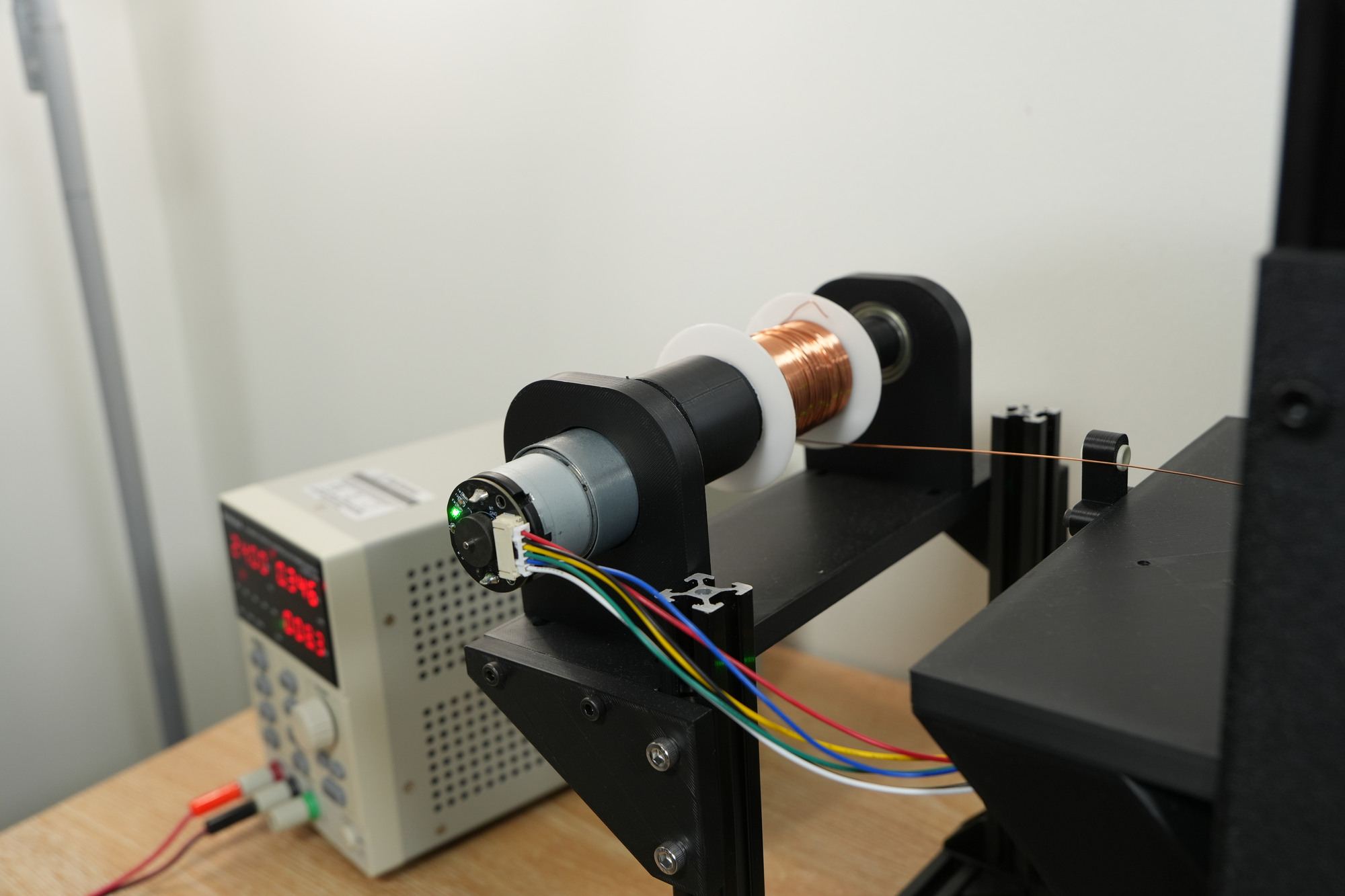
Next was tension. If the wire goes on with no tension, it just tangles and turns into a mess. My plan was to wrap the wire around a capstan driven by a DC motor working as a brake, pulling back against the winding. A capstan can hold several wires wrapped around it together, which would let me wind a stator with multiple wires in parallel.
Using a DC motor as a brake works because its torque is proportional to its current. Set the current, and you've set the pull on the wire.
Electronics
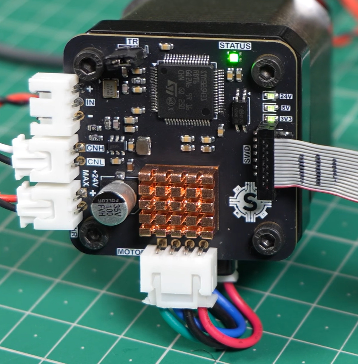
Every axis is driven by a stepper motor, and the drivers are the same custom stepper drivers my brother Steve and I made for our 6-DOF robot arm. That saved designing a new set of boards, and it turned out to matter later, because those drivers have magnetic encoders on them.
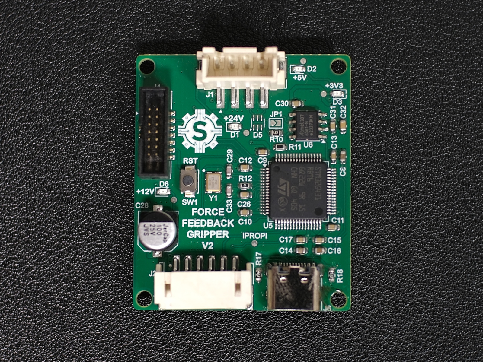
The tensioner's DC motor is run by the controller board from our force-controlled gripper. That board already holds a DC motor at a set current, which is exactly what the tensioner needs.
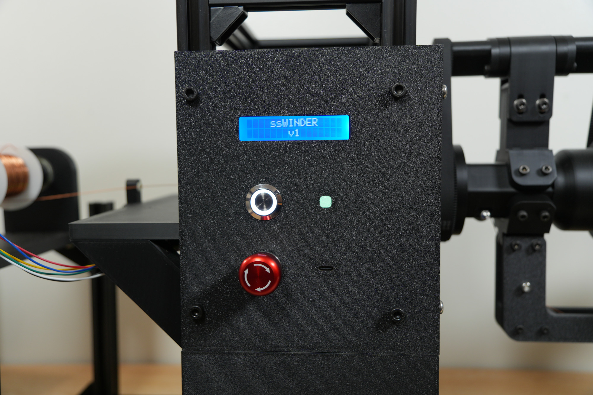
The Finished Machine
Orthocyclic Winding
How the wire is stacked matters as much as the machine. I'm using orthocyclic winding, which packs round wire as tightly as it can go. If you look at a cross-section of the coil, the wires sit in a honeycomb pattern, like oranges stacked in a crate.
Every turn runs straight and parallel to the ones next to it, and all of the sideways movement happens in one short crossover window on one end face of the tooth. For about 300° of each flyer turn, the traverser holds still, so the wire lays straight across both sides of the slot and the other end face. Then, in a 60° window, it moves the stator exactly one wire diameter \(d\) to set up the next turn.
First layer
The first layer is wound slowly against the root wall, with turns at \(0.5d\), \(1.5d\), \(2.5d\), and so on. It has to be perfect, because every layer above it follows the grooves it makes.
At the end of a layer, the traverser moves half a wire diameter instead of a full one. That drops the first turn of the next layer into the groove next to the wall, and then the direction reverses. That's why the odd layers sit at \(1d\), \(2d\), \(3d\) and have one fewer turn than the even layers.
It's also why each layer adds less than a full wire diameter of height. A wire resting in the groove between two others forms an equilateral triangle with them, so its center sits only this far above theirs:
Jaw clearance
The jaw feeds the wire in, and it has to stay clear of everything already wound. Its height changes with the layer, because the traverse direction flips every layer:
- Layer 0: the jaw slides on the bare tooth.
- Odd layers: the traverser carries the turns that were just laid back under the jaw's lip, so the jaw has to clear the top of the current layer.
- Even layers: the turns move away from the lip, so it only rides over the layer below, and the jaw can stay where it is.
So the jaw only moves when it's going into an odd layer. It jumps two layer heights during the crossover window of the last turn of the even layer, and then holds through the next even layer. For an odd layer \(n\), the jaw height is the top of that layer plus a small clearance \(c\):
So the jaw sits at zero on layer 0 and jumps up to clear layer 1 when it moves into it. After that, it steps up by two layer heights (\(1.732\, d\)) going into each odd layer.
Testing
The first test taught me a few things quickly. Wrapping the wire around the capstan was a pain, and it turned out I didn't need it at all: running the spool motor itself as the brake gave plenty of tension. So the capstan and its motor came out, and the wire now comes straight off the spool. The spool motor runs on the same gripper controller board, so the electronics didn't change.
Next, the wire kept missing the tooth. When the stator rotated to the next tooth, it didn't land in exactly the right spot, so the wire piled up outside the tooth instead of winding onto it. My best guess is that the stepper was skipping steps, since steppers run open loop and never know when they've missed one. The stepper drivers from the robot arm have magnetic encoders on them, so I used the encoders to correct the position every time the stator moves to a new tooth.
The last problem was the second layer. The first layer went on neatly, but the second came out disorganized. I added a holder to stop the stator moving around during winding, which helped a little but didn't fix it. What actually fixed it was making a few tweaks to the winding parameters.
Here it is winding with all of those fixes in:
What's Next
- Improve the winding algorithm, so the winds come out reliably every time and the machine can wind faster.
- Wind a full stator from start to finish.
Conclusion
Most of the problems so far haven't been about the mechanism. Getting the wire to lay down neatly has come down to details: where the stator actually is, how hard the wire is pulled, and how fast it goes on. I'll update this page once it's winding complete stators.
Thanks for reading!